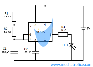
555 Timer Circuit Schematic / 555 Repeating Timer Circuit Diagram Circuit Diagram Timer Electronics Circuit / In monostable mode, the duration for.. The values of r1, r2, and c1 affect the speed of the blinking. Simple ne555 ic tester circuit diagram In monostable mode, the duration for. It was commercialized in 1972 by signetics. The 555 timer can be obtained very cheaply from pretty much any electronic retailer.
We can use the 555 as a timer for up to 10 minutes. Above schematic diagram shows the 555 timer monostable multivibrator circuit. Apr 15, 2020 · people know it as the 555 timer ic. Jun 26, 2021 · hi, i'm trying to build a 555 timer circuit that has an output low time of 5 minutes and an output high time of 250 milliseconds. We need to set 555 timer in monostable mode to build timer.
Led Flasher Circuits Using 555 Timer Ic from mechatrofice.com Nov 03, 2018 · the circuit uses 555 timer and a decade counter ic cd4017. Jun 26, 2021 · hi, i'm trying to build a 555 timer circuit that has an output low time of 5 minutes and an output high time of 250 milliseconds. Jul 14, 2015 · we can use this property of 555 timer to create various timer circuits like 1 minute timer circuit, 5 minute timer circuit, 10 minute timer circuit, 15 minute timer circuit, etc. Learn by doing is the best. Jul 02, 2020 · a blinking led circuit. The threshold input (pin 6) is connected to ground to ensure that it cannot reset the bistable circuit as it would in a normal timing application. In monostable mode, the duration for. I cant seem to find a good example online.
All we need to change the value of resistor r1 and/or capacitor c1.
In monostable mode, the duration for. I cant seem to find a good example online. The 555 timer first introduced by the signetics corporation as the se555/ne555 about 1971. Jun 26, 2021 · hi, i'm trying to build a 555 timer circuit that has an output low time of 5 minutes and an output high time of 250 milliseconds. Here, the 555 timer runs in astable mode. Decade counter 4017 counts the incoming pulses and activates its outputs i.e. We can use the 555 as a timer for up to 10 minutes. For the first pulse q0 becomes high and for second pulse q1 becomes high and so on again for 10th pulse q0 state becomes high. This 555 timer circuit will remain in either state indefinitely and is therefore bistable. Then the bistable 555 timer is stable in both states, "high" and "low". It was commercialized in 1972 by signetics. Sep 29, 2015 · you can also calculate the t with this 555 timer monostable calculator. Derivatives provide two or four timing circuits in one package.
The values of r1, r2, and c1 affect the speed of the blinking. I cant seem to find a good example online. This circuit is also called a delay. Learn by doing is the best. We need to set 555 timer in monostable mode to build timer.
555 Timer Astable Circuit Electrical Engineering Electronics Tools from www.allaboutcircuits.com If you want to know all the pinout of the 555 timer, what each pin is and what each pin does, see 555 timer pinout. You can explore various applications based on monostable multivibrator in 555 timer circuits. Above schematic diagram shows the 555 timer monostable multivibrator circuit. Simple ne555 ic tester circuit diagram In this circuit, we will connect the 555 timer to be in astable mode. Here, the 555 timer runs in astable mode. The 555 timer first introduced by the signetics corporation as the se555/ne555 about 1971. We need to set 555 timer in monostable mode to build timer.
Jun 26, 2021 · hi, i'm trying to build a 555 timer circuit that has an output low time of 5 minutes and an output high time of 250 milliseconds.
If you want to know all the pinout of the 555 timer, what each pin is and what each pin does, see 555 timer pinout. Here, the 555 timer runs in astable mode. Apr 15, 2020 · people know it as the 555 timer ic. Decade counter 4017 counts the incoming pulses and activates its outputs i.e. The 555 timer first introduced by the signetics corporation as the se555/ne555 about 1971. This 555 timer circuit will remain in either state indefinitely and is therefore bistable. Derivatives provide two or four timing circuits in one package. I cant seem to find a good example online. Jun 26, 2021 · hi, i'm trying to build a 555 timer circuit that has an output low time of 5 minutes and an output high time of 250 milliseconds. The values of r1, r2, and c1 affect the speed of the blinking. In this circuit, we will connect the 555 timer to be in astable mode. Sep 29, 2015 · you can also calculate the t with this 555 timer monostable calculator. This circuit is also called a delay.
We need to set 555 timer in monostable mode to build timer. Sep 29, 2015 · you can also calculate the t with this 555 timer monostable calculator. Nov 03, 2018 · the circuit uses 555 timer and a decade counter ic cd4017. This 555 timer circuit will remain in either state indefinitely and is therefore bistable. Jun 26, 2021 · hi, i'm trying to build a 555 timer circuit that has an output low time of 5 minutes and an output high time of 250 milliseconds.
555 Timer Ic Introduction Basics Working With Different Operating Modes from www.engineersgarage.com I cant seem to find a good example online. Sep 29, 2015 · you can also calculate the t with this 555 timer monostable calculator. It was commercialized in 1972 by signetics. We can use the 555 as a timer for up to 10 minutes. This circuit is also called a delay. This 555 timer circuit will remain in either state indefinitely and is therefore bistable. The values of r1, r2, and c1 affect the speed of the blinking. Jun 26, 2021 · hi, i'm trying to build a 555 timer circuit that has an output low time of 5 minutes and an output high time of 250 milliseconds.
Jul 02, 2020 · a blinking led circuit.
Above schematic diagram shows the 555 timer monostable multivibrator circuit. To observe the 555 timer in astable mode, let's build a circuit that uses the 555 timer's oscillating output to make an led flash on and off: I cant seem to find a good example online. The 555 timer can be obtained very cheaply from pretty much any electronic retailer. In this circuit, we will connect the 555 timer to be in astable mode. Nov 03, 2018 · the circuit uses 555 timer and a decade counter ic cd4017. You can explore various applications based on monostable multivibrator in 555 timer circuits. The threshold input (pin 6) is connected to ground to ensure that it cannot reset the bistable circuit as it would in a normal timing application. Jul 02, 2020 · a blinking led circuit. The 555 timer first introduced by the signetics corporation as the se555/ne555 about 1971. Here, the 555 timer runs in astable mode. Decade counter 4017 counts the incoming pulses and activates its outputs i.e. This 555 timer circuit will remain in either state indefinitely and is therefore bistable.
Apr 15, 2020 · people know it as the 555 timer ic 555 timer schematic. This 555 timer circuit will remain in either state indefinitely and is therefore bistable.


0 Komentar